Gears | Contact ratio
This article explains the meaning of the transverse-, the axial-, and the total contact ratios (sometimes referred to as overlap). The contact ratios are nominal values that assume ideal contact between two involute gears. In reality, the actual contact ratios differ slightly from the nominal values due to deformation, deviations from the ideal gear geometry, and position deviations at the system level. The gear transmission error must be as small as possible to minimize acoustic excitation. The contact ratios have a significant influence on the smallest achievable values of transmission error.
Total contact ratio εγ
The total contact ratio describes how many teeth are in active contact on average over time. The total contact ratio is a key parameter for smoothing out the variations of the gear mesh stiffness and thus for minimizing transmission error. It is calculated as the sum of the transverse contact ratio and the axial contact ratio:
εγ = εα + εβ.
Integer values are often targeted for εα and εβ, as this means that the sum of the theoretical contact line lengths across the active flanks does not change over time. For values of the total contact ratio of εγ > 2.5, the influence of a further increase in the overlap is only minor.
Transverse contact ratio εα
The transverse contact ratio describes the number of tooth pairs that are in active contact on average over time in any arbitrary transverse section of the gear mesh. Practical gears are usually designed in a way that several tooth pairs come into contact as they travel along the line of contact (i.e., εα > 1.0). Fig. 1 illustrates such a transverse section of a gear mesh between a pinion and a wheel with important gear mesh parameters. If two geometrically perfect involute gears are in load-free engagement, the contact points of the active flanks travel along the line of contact in each transverse section. The meshing starts at point A (i.e., start of active profile) and ends at point E (i.e., end of active profile). Between these points lies the path of contact with a length of gα. The path of contact is therefore the actively used part of the line of action. The distance between the contact points is the transverse base pitch denoted by pet.
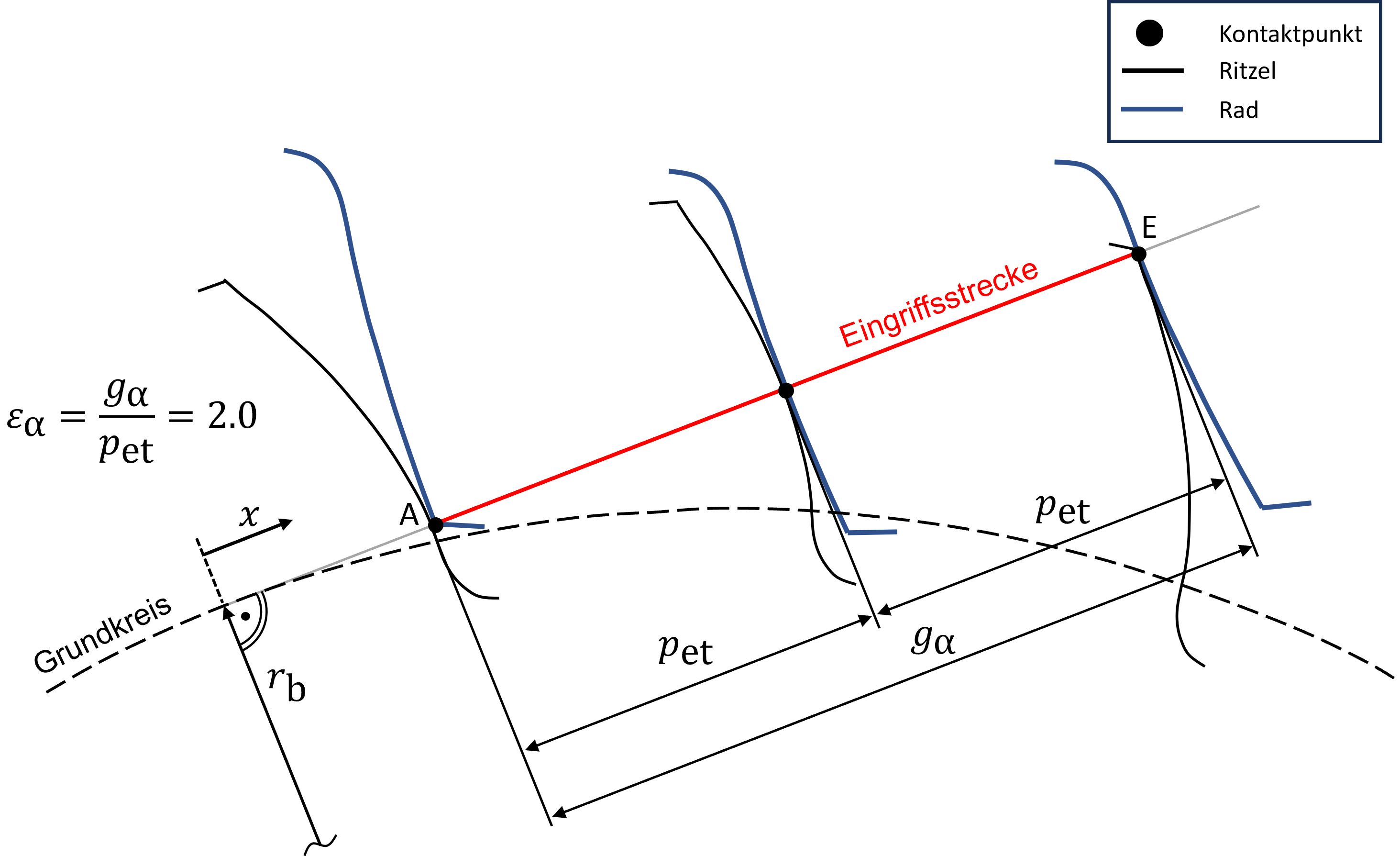
In Fig. 1, the gearing has been designed so that there are exactly three contact points on the line of action. The first contact point lies at point A, the second contact point is exactly in the middle of the path of contact, and the third contact point coincides with point E. At the illustrated instance of time, a pair of teeth engages at point A while at the same time a pair of teeth leaves the contact at point E. Thus, for a brief moment, three pairs of teeth are engaged. If the gears now rotate a small increment further, two pairs of teeth remain in contact. On average, exactly two pairs of teeth are in contact in the illustrated transverse section, so the transverse contact ratio is εα=2.0. For non-integer values of the transverse contact ratio, such as for the range 1.0 <= εα <= 2.0, which is highly relevant in practice, alternately one or two pairs of teeth are active simultaneously, depending on the current position in mesh of both mating gears.
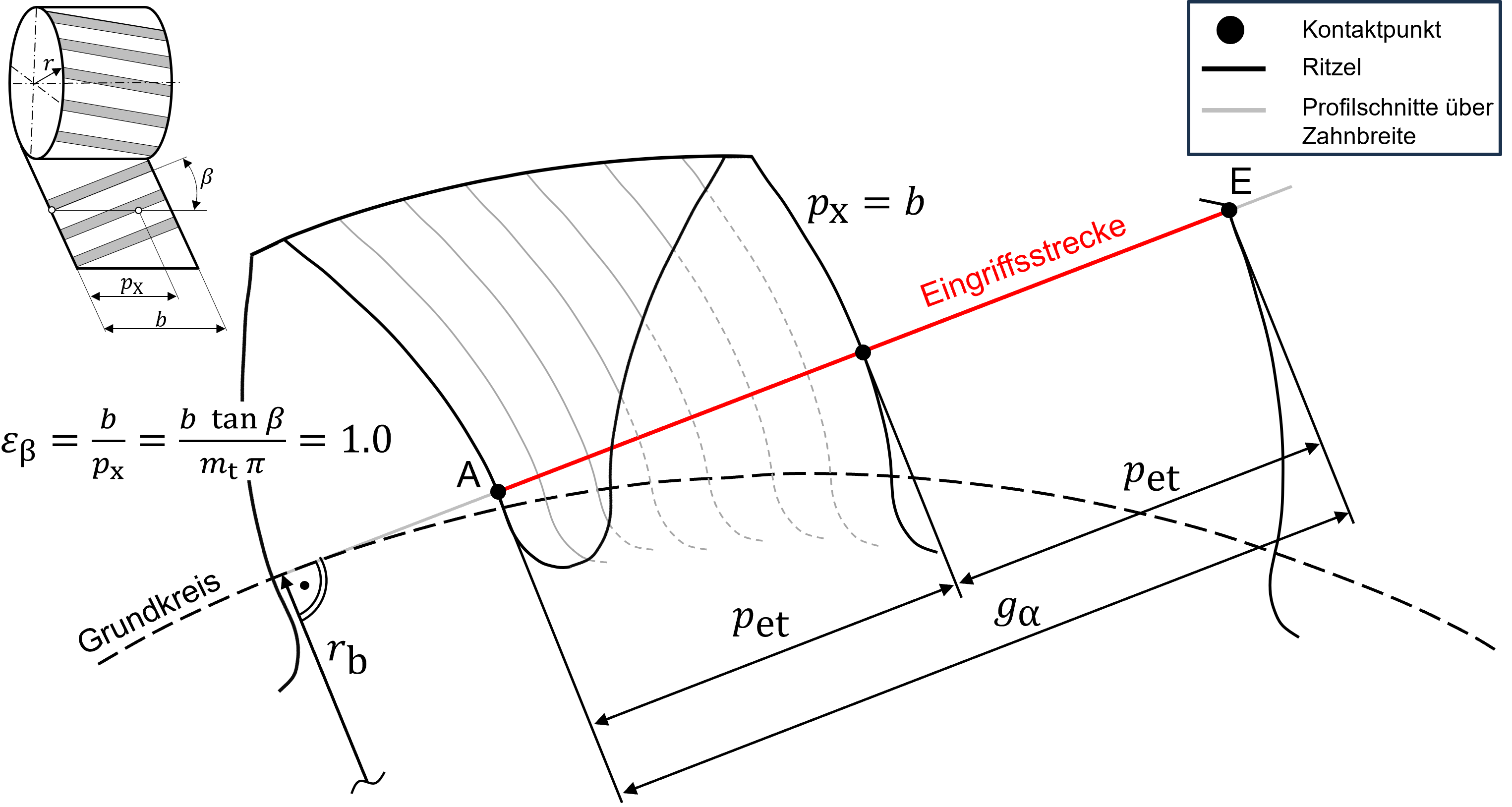
Axial contact ratio εβ
The axial contact ratio describes the average number of teeth that are additionally in active engagement due to the helix angle β. For spur gears with straight teeth, εβ=0 generally applies. The gearing shown in Fig. 2 is designed so that the axial contact ratio is exactly εβ=1.0. This means that the axial pitch is equal to the tooth width pX=b. The transverse section shown on the front coincides with the face profile on the back of the gear. The profile on the back is one pitch further than the profile on the front. The gray profile lines indicate how the profile traces of the helical tooth (generated by several transverse cuts along the gear width) travel along the path of contact. The helix angle β is often determined by the required axial contact ratio and the tooth width b. For a given axial contact ratio εβ, increasing the tooth width reduces the required helix angle.