Tooth Flank Fracture
A Novel 2D-3D Micro-Macro Approach for TFF Prediction
Rauch A. D.
Tooth flank fracture (TFF) is a highly relevant and problematic mode of failure in many applications of cylindrical gears and bevel gears, such as in wind turbines, marine gearboxes, truck transmissions & differentials, as well as in heavy duty industrial gearboxes. TFF leads to a sudden catastrophic failure of the system at loads below the fatigue limits for pitting (contact fatigue) and tooth root fracture. Reliable prediction of the TFF risk has high economic impact especially in applications in which extensive testing is unfeasible due to large size or small production numbers.
Available computational methods for TFF prediction are 1D/2D, since a full 3D analysis of the tooth contact and the stress history in the tooth interior is not feasible in practical applications. However, certain effects can only be captured in 3D. Therefore, we suggest a novel computational method which efficiently incorporates the 3D physics by leveraging a mixed-dimensional multi-scale approach. An important aspect of our method is the interface to SMT's MASTA software (link). Masta's efficient Loaded Tooth Contact Analysis (LTCA) eliminates the need for a complex detailed FE contact analysis, with only minimal loss of accuracy [1]. MASTA enables the modelling of the whole transmission system and the evaluation of the system deflection under load which is fed to the LTCA as boundary condition. This allows to incorporate the effect of deformation and manufacturing deviations on the contact stresses and consequently on the risk of TFF/TIFF.


Highest fidelity TFF method
- Highly efficient 3D FEM analysis of TFF & TIFF.
- Implemented in MAHLE ZG's simulation library ZGearSim.
- MASTA's efficient LTCA avoids costly 3D-FEM contact analysis.
- Considers system deformation and flank micro-modification.
- Incorporates 3D effects from case hardening.
- Includes realistic shear & normal stresses from skew tooth bending.
3D-Macro Model
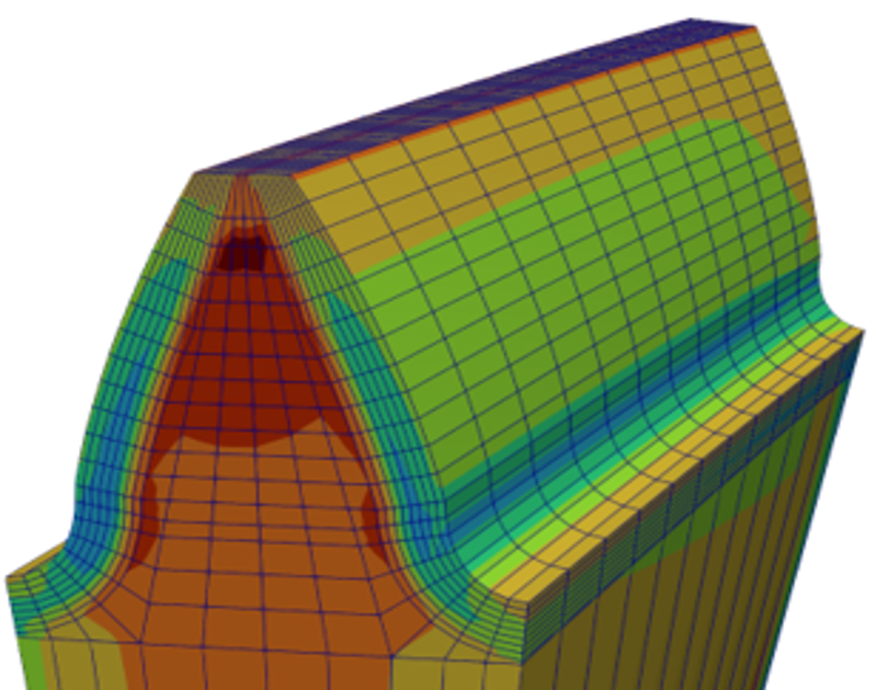
- Residual & bending stresses evaluated on 3D macro FEM model.
- Reasonably coarse 3D FEM mesh with flank aligned boundary mesh.
- Accurate evaluation of load stress history.
- Fast solution times of macro model.
2D-Micro Model
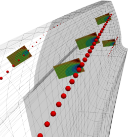
- Contact stress fields evaluated on 2D micro discretization beneath each contact point.
- Hertzian contact stress model for plane-strain and/or plane-stress.
- Fast evaluation of contact stresses using LTCA results.
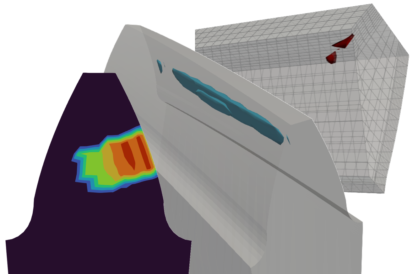
Damage localization in 3D
- Detailed presentation of TFF/TIFF risk in 3D.
- Several multiaxial fatigue criteria implemented.
- Assessment of TFF/TIFF risk and localization of crack initiation w.r.t.:
- Load,
- Manufacturing deviations,
- Microgeometry design,
- etc.
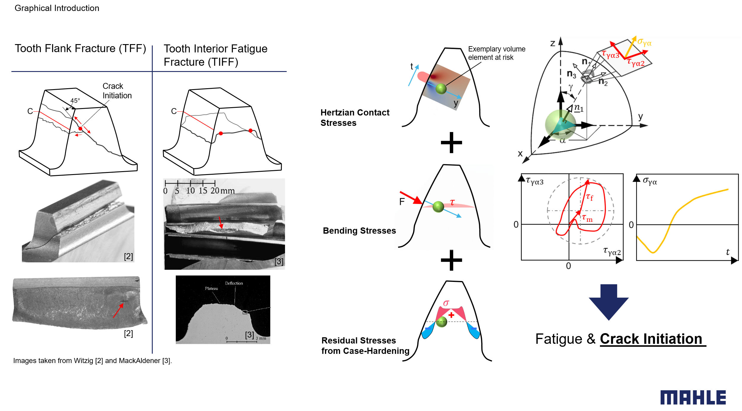
TFF is the result of tooth internal fatigue
Tooth flank fracture (TFF) and tooth interior fatigue fracture (TIFF) are two related types of failure. Typical examples are documented, e.g., by Witzig [2] and MackAldener [3]. TFF occurs in gears with single flank loading, whereas TIFF is predominantly found in idler gears which are loaded on both tooth flanks. Despite the different damage phenomenologies the underlying material mechanical root cause for crack initiation is the same for both damage types. The material in the interior of a loaded tooth is stressed by the dynamic contributions from Hertzian contact and from tooth bending, as well as by the static residual stresses resulting from case hardening. In any arbitrarily oriented plane around any material point the time histories of the shear and normal stress cycles can be evaluated. These dynamic stresses fatigue the material and may lead to the formation of a tooth internal crack. The compressive residual stresses near the surface of case -hardened gears have a positive effect on the durability, but lead to tensile stresses in the core. TFF & TIFF are often initiated close to the case/core-boundary where the negative effects of tensile residual stresses and increased shear stresses from tooth bending act together.
Method Overview
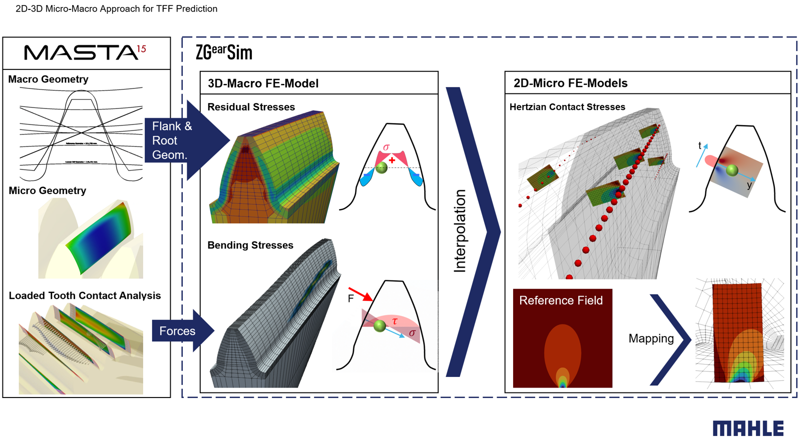
Input to MZG's TFF method are the gear geometry and the gear mesh contact forces. In the case of cylindrical gears the geometry is modeled with SMT's MASTA and MASTA's efficient loaded tooth contact analysis (LTCA) is performed for the desired load scenarios. The gear geometry is exported in STEP format and is the basis of the automated mesh generation process implemented in ZGearSim. The gear mesh forces for each contact point on each contact line for each simulated relative position of the mating gears are exported from MASTA and fed to ZGearSim.
3D-Macro model: The macroscopic 3D stresses from case hardening and tooth bending are evaluated on a reasonably coarse 3D FEM mesh of a single tooth. The residual stresses from case hardening are obtained from the prescribed transformation strain profile normal to the gear surface. The required stress-history from tooth bending is obtained from consecutive solutions of the macro FE model subjected to the contact forces of each loaded contact line.
2D-Micro model: The microscopic contact stresses are solved on a set of individual 2D micro FE discretizations which are constructed beneath each loaded contact point. Each micro discretization is subjected to a Hertzian pressure distribution with a maximum pressure calculated from the associated LTCA contact force.
By superposition of the micro- and macro stress contributions an accurate stress-history under the loaded tooth flank is evaluated. The described methodology allows short evaluation times while maintaining the full 3D information with only marginal loss of accuracy compared to a cumbersome full 3D contact analysis.
Models for material, stress, and fatigue
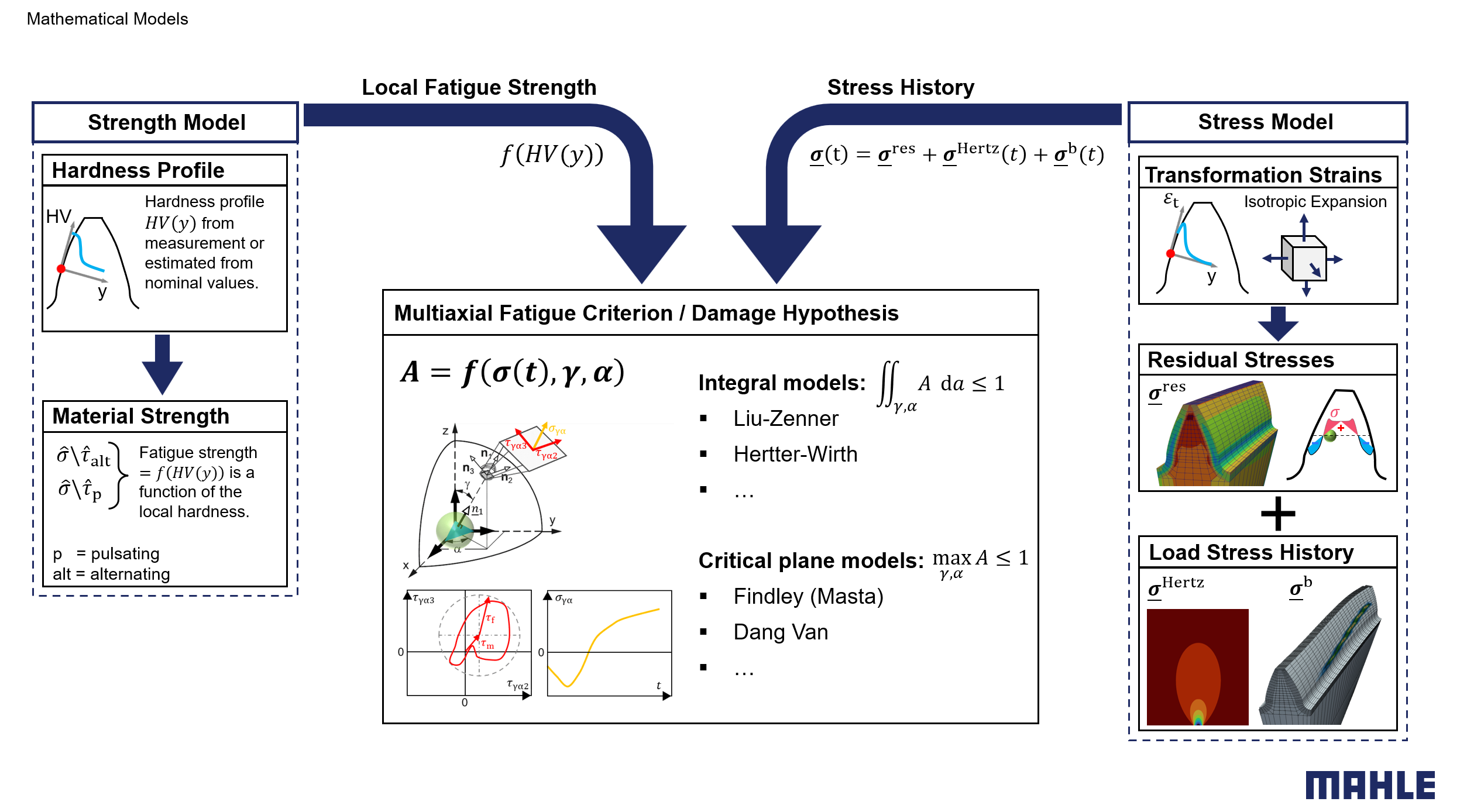
The strength model relates the fatigue limits for alternating and pulsating shear and normal stresses to the local hardness values underneath the gear surface. The hardness profile normal to the surface may be measured or estimated by well-known models such as those by MackAldener, Lang, or Thomas [3,4]. The stress model assumes linear superposition of the static residual stresses and the dynamic stresses from tooth bending & contact.
The derived local fatigue properties and the local stress-history at each point considered in the material are the input variables for a multiaxial fatigue criterion. Mean and fluctuating components of both shear and normal stresses in required section planes at every considered material point are evaluated. Various integral- and critical plane approaches for multiaxial fatigue have been proposed to relate those stress components to material fatigue. Integral approaches such as those by Liu-Zenner [5] and Hertter-Wirth [6,7] evaluate an integral value from the material utilization in any section plane at any material point. Critical plane criteria such as those by Findley [8] or Dang Van [9] assume the plane with maximum utilization alone to be relevant. These and more models are available in ZGearSim.
TFF risk & localization of crack initiation
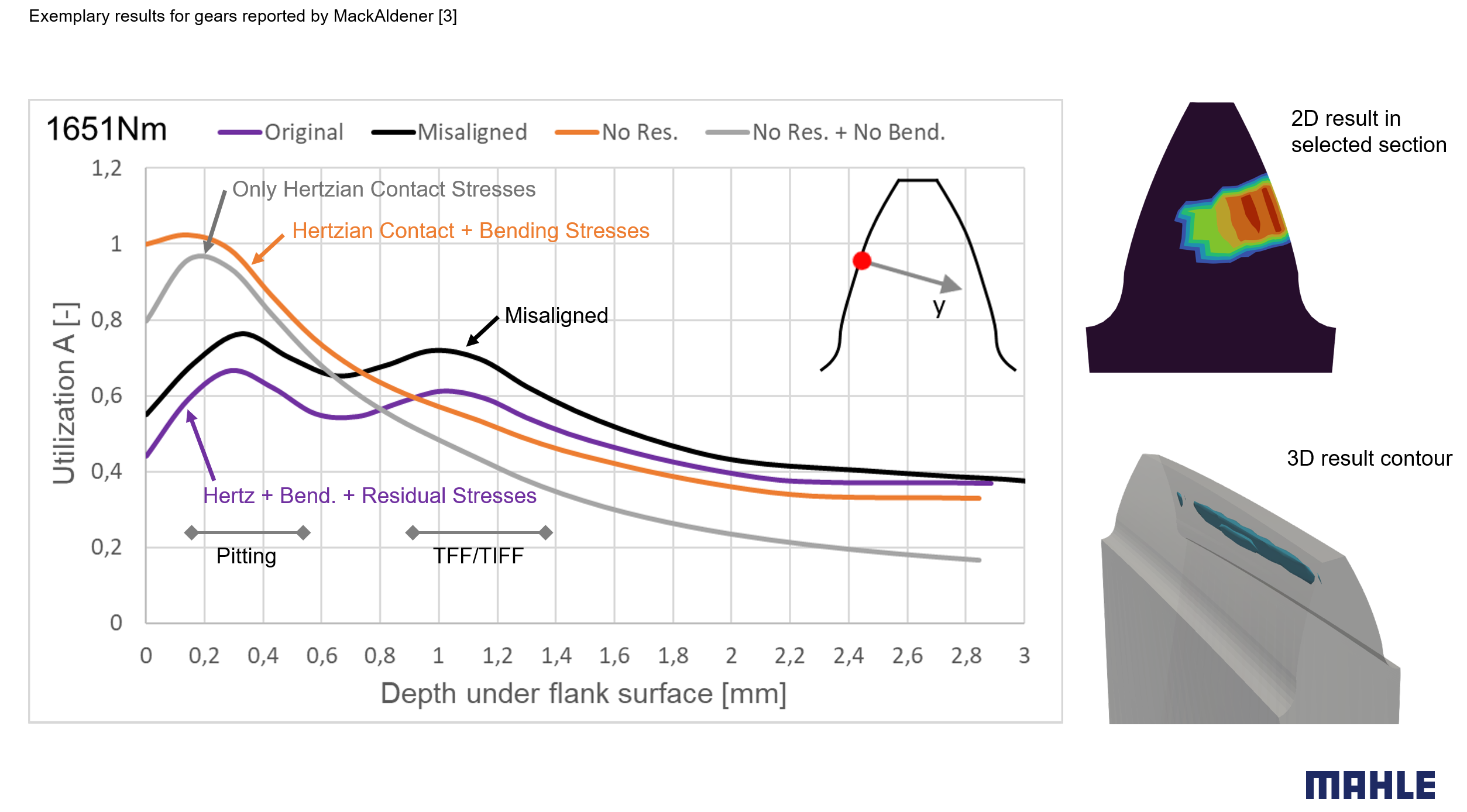
The material utilization is evaluated along the surface normals beneath each considered contact point and is mapped to the macro FE mesh. The residual stresses typically have a major influence on the results. Sites of high utilization in close proximity to the flank surface are at risk of pitting damage (contact fatigue). Tooth flank fracture and tooth interior fatigue fracture originate typically from deeper regions close to the case-core boundary. Critical regions may travel due to system deflection or manufacturing deviations. Owed to the 3D nature of our TFF method it is possible to present the precise location of the material volume with highest utilization. Also common 2D slices with colored contours can be generated.
References
| [1] Langlois P. et al. (2016, July). Hybrid Hertzian and FE-Based Helical Gear-Loaded Tooth Contact Analysis and Comparison with FE. Geartechnology, 54-63. |
| [2] Witzig J. (2012). Flankenbruch - Eine Grenze der Zahnradtragfähigkeit in der Werkstofftiefe. Dissertation. |
| [3] MackAldener M. et al. (2001). Tooth Interior Fatigue Fracture - computational and material aspects. International Journal of Fatigue, 23, 329-340. |
| [4] Thomas J. (1998). Flankentragfähigkeit und Laufverhalten von hartfeinbearbeiteten Kegelrädern. Dissertation. |
| [5] Liu J. (1993). Berechnung der Dauerschwingfestigkeit bei mehrachsiger Beanspruchung – Teil 1-3. Materialwissenschaft und Werkstofftechnik, 24, 240-249. |
| [6] Hertter T. (2003). Rechnerischer Festigkeitsnachweis der Ermüdungstragfähigkeit vergüteter und einsatzgehärteter Stirnräder. Dissertation. |
| [7] Wirth C. (2008). Zur Tragfähigkeit von Kegelrad- und Hypoidgetrieben. Dissertation. |
| [8] Findley W.N. (1957). Fatigue of metals under combinations of stresses. Trans. ASME, 79, 1337-1347. |
| [9] Dang Van K. et al. (1999). High-Cycle Metal Fatigue. Springer. |
Having a hard time meeting your durability targets?
Contact us for a free initial consultation.