Plastic Gears
Challenges and Possibilities of Flank Form Modifications in Plastic Gears
Koop M., Kötz C., Tründelberg E.


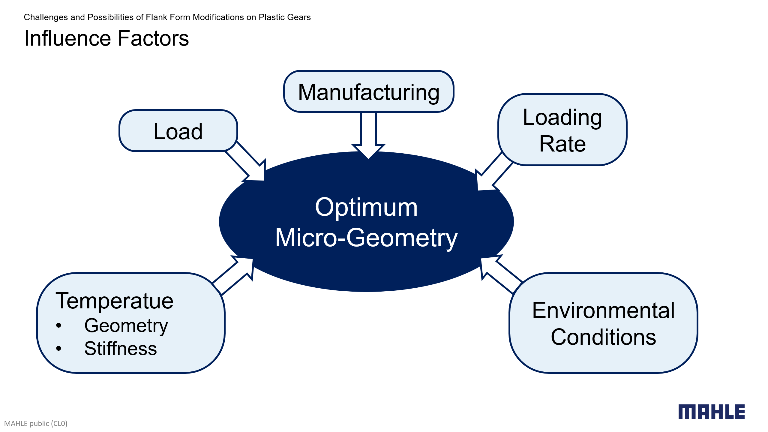
Theoretically, perfect and ideally rigid involute gears ensure power transmission without transmission errors, i.e., both mating gears rotate at constant speeds. In practice, a non-constant mesh stiffness, as well as deformations of the mating tooth flanks and the system impair ideal, uniform power transmission. This may result in excessive contact pressures and high transmission errors, potentially causing acoustic problems [4]. To compensate for this, in practice, flank form modifications at the micrometer scale are manufactured. Since deformations are load-dependent, a micro-geometry can only be optimized for a specific load point. In applications with broader load spectra, a “robust” micro-geometry design must be pursued, meaning that load changes and manufacturing tolerances have smallest possible impact on transmission behavior.
While micro-geometry modifications in steel gears, especially ground gears, are state of the art, only a few modifications, such as tip reliefs are usually applied to plastic gears. Designing micro-geometry modifications in plastic gears is particularly challenging due to the nonlinear, viscoelastic, and highly temperature-dependent material properties of plastics, such as POM and PEEK. In this study, the influence of these plastics-specific properties on the micro-geometry design are illustrated by analyzing the simulation results of exemplary plastic gear stages. Production spread within specified tolerances is considered. Results for peak-to-peak transmission errors vs. load are analyzed. Finally, general recommendations are given for optimizing flank form modifications across different temperatures and loads.
Micro-Geometry Optimization in Plastic Gears
- The special properties of plastics pose a major challenge for the optimization of gears.
- A non-linear and highly temperature-dependent stress-strain curve complicates the design for broader operating conditions.
- Viscoelasticity results in the deformation-rate dependency of the stiffness.
- Humidity in the environment and the absorption of water becomes an issue with plastics.
- Thermal expansion leads to deviations of the gear mesh parameters when different material are used for pinion and wheel.
- Injection molding has a significant impact on the achievable accuracy, especially in the case of fiber-reinforced plastics.
Statistical Analysis
- Micro-geometries optimized for specific combinations of load and temperature often perform poorly under other operating conditions.
- Finding a good compromise for the whole spectrum of loads, temperatures, and form deviations from manufactuing is no trivial task.
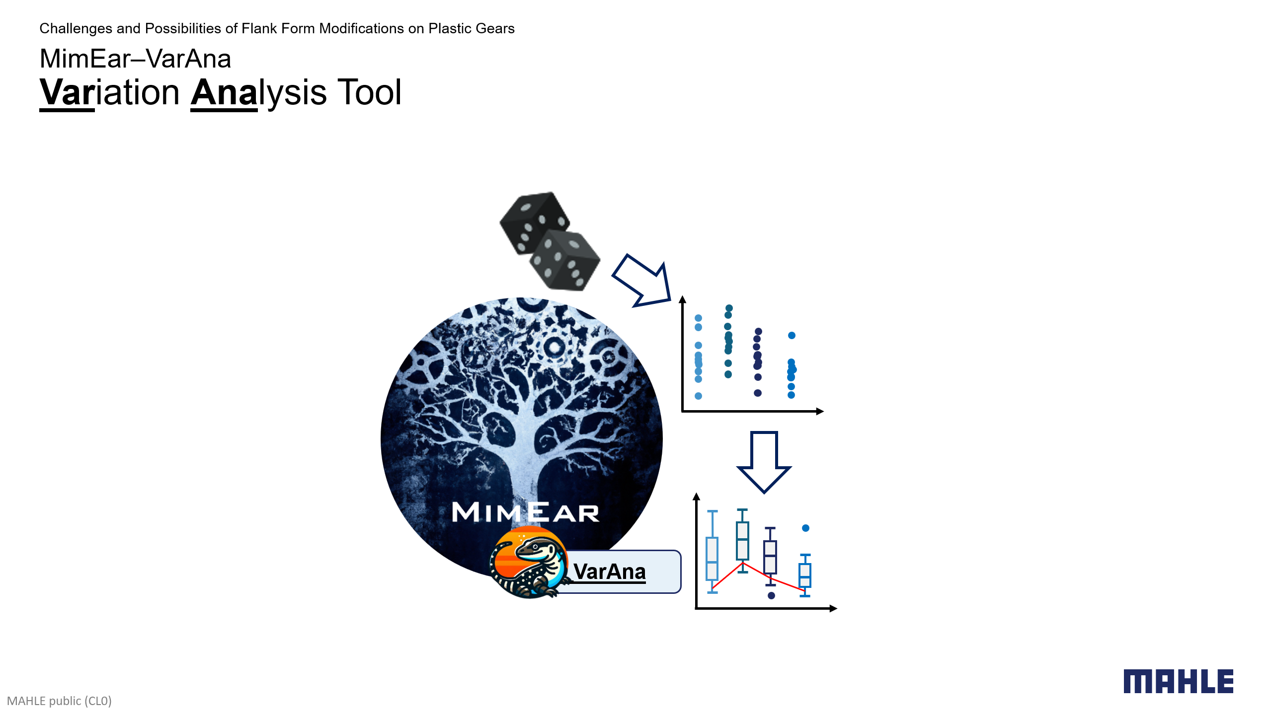
- MZG uses the MimEar module VarAna to crystallize meaningful results from large data sets obtained from large-scale parametric studies.
- VarAna helps to identify variants which fulfill specified constraints, such as smallest average target values for weighted combinations of different categories.
Influencing Factors on the Transmission Behavior of Plastic Involute Gears
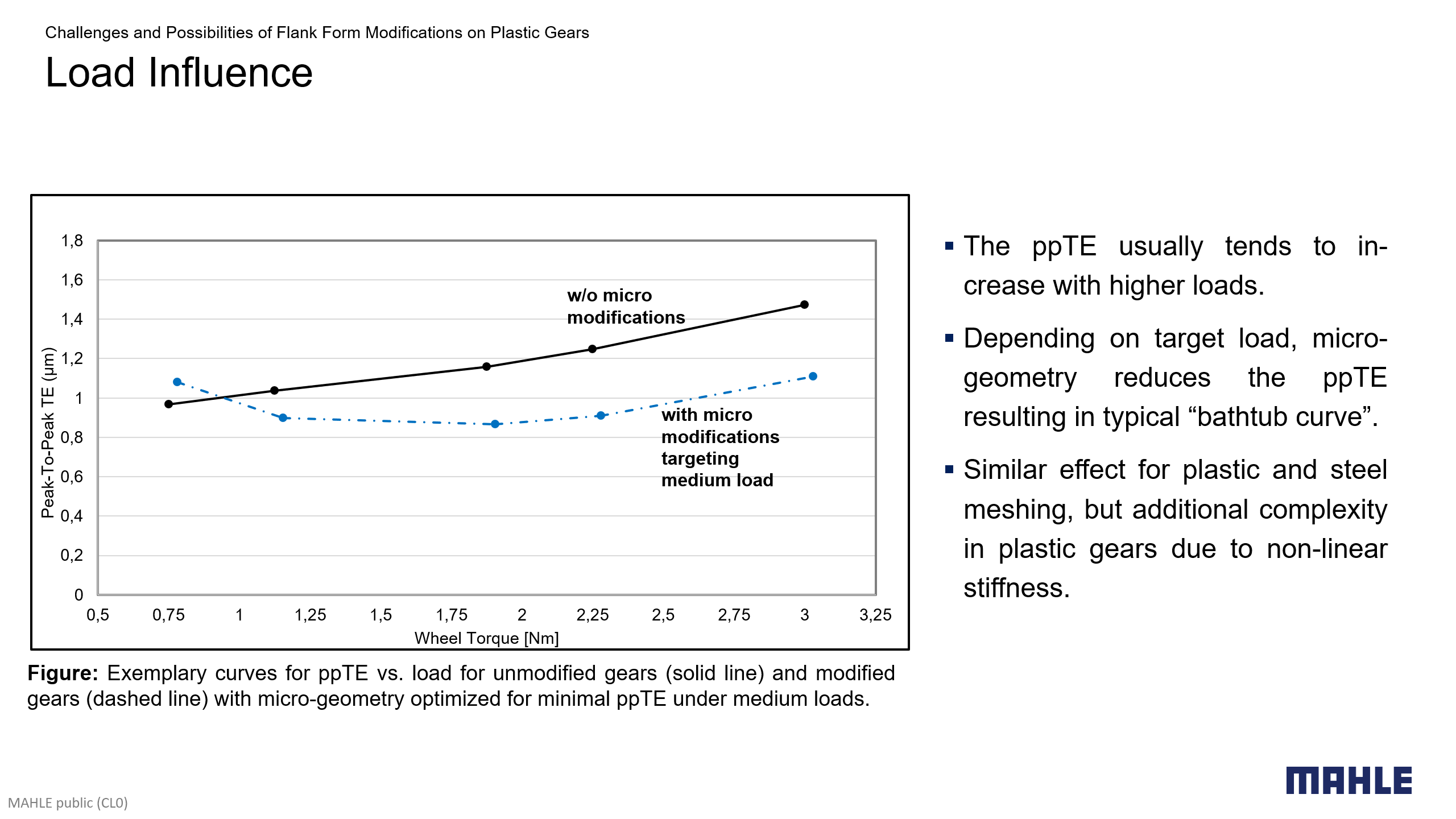
Load Influence
Applying torque causes deformations in the gear mesh which depend on the mesh stiffness. Mesh stiffness, in turn, is a function of the roll distance as the current actual number of teeth in contact and the lever arms of the contact forces vary along the path of contact. The smaller the variation in mesh stiffness the smaller the transmission error (TE). Any micro-geometry design can minimize TE only for one specific load. When considering multiple load levels, a compromise must be made. In the case of plastic gears, load dependence is even greater than with steel gears due to the material’s nonlinear stiffness, which exhibits a decreasing secant modulus as the load increases. Flank form modifications in plastic gears must therefore be designed in such a way that they are even more tolerant of load variations than steel gears. To achieve this, an optimal operating range (e.g., 2/3 of the maximum load) is defined, and a micro-geometry is designed accordingly. This results in a characteristic “bathtub curve” for transmission errors vs. load. The minimum of this curve can be shifted by adjusting the micro-geometry.
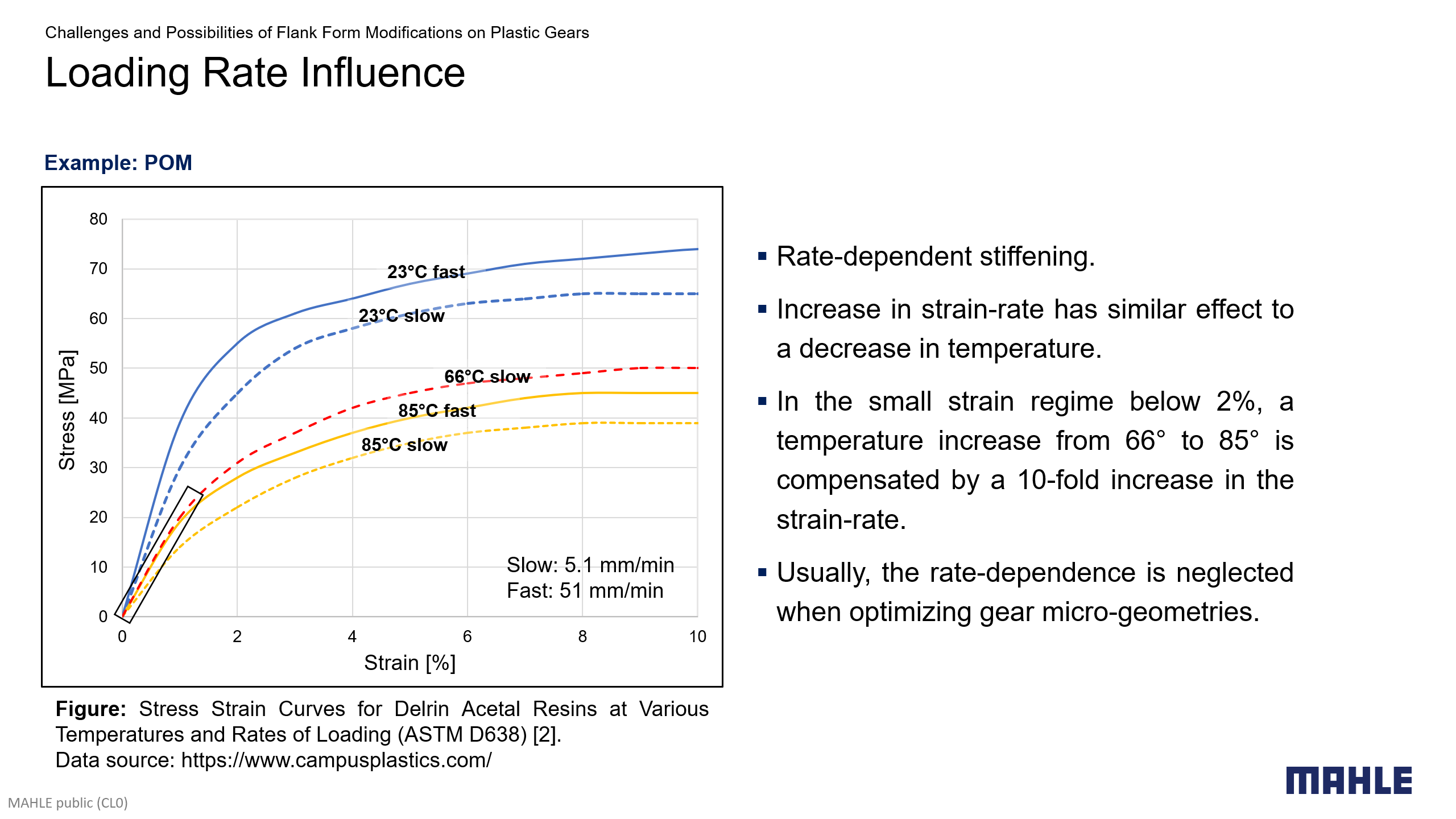
Loading Rate Influence
In steel gears, the influence of loading rate is negligible, whereas in plastic gears the speed of load (and deformation) increase or decrease has a significant impact due to the pronounced viscoelastic behavior of plastic materials. A higher loading rate (and deformation rate) has a stiffening effect which is similar to a temperature decrease. For example, the relevant secant moduli for small strain rates are nearly identical for 85°C at a deformation rate of 51 mm/min and 66°C at a rate of 5.1 mm/min. Micro-geometry design should therefore consider the rate-dependencys if necessary, although its effects are often minor compared to temperature changes in typical applications and can usually be neglected.
Environmental Influence
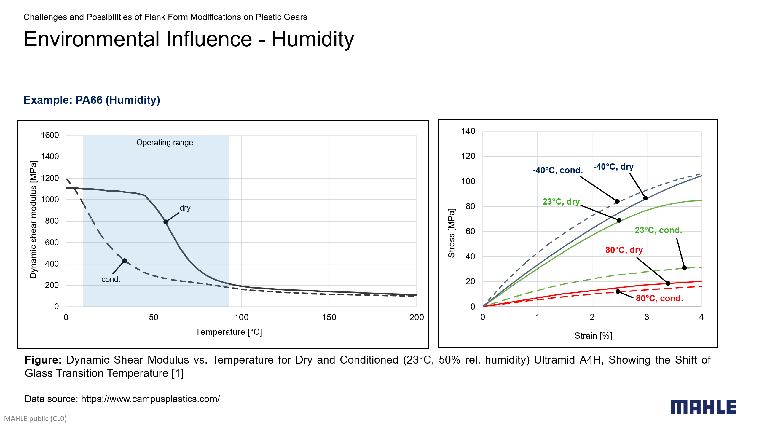
Unlike metals, plastics absorb moisture from the environment, leading to swelling and changes in mechanical properties. Plastics such as POM or PEEK absorb only minimal amounts of water (e.g., POM max. 0.9% [1; Delrin 100nc10]), while polyamides are generally hydrophilic due to their hydrogen bonds and can absorb large amounts of water [3; 366f.]. This causes volume expansion similar to thermal expansion and corresponding geometry changes. Additionally, the glass transition temperature shifts to lower temperatures.
Furthermore, the temperature range in which the steep decline in shear modulus (due to glass transition) is observed shifts to lower temperatures. This is illustrated for PA66 for which the transition is shifted from approx. 50°C-70°C (dry state) to approx. 0°C-25°C (conditioned state). Thus, for 23°C the stress-strain curves differ significantly between the dry and the conditioned states. For cold temperatures (e.g. -40°C) or high temperatures (e.g. 80°C) the material is stable in either the hard or the soft regime and the differences in stiffness between dry and conditioned states become small. In fiber-reinforced plastics, anisotropic geometry changes due to swelling can affect the gear mesh, particularly in the case of different materials for pinion and wheel.
Temperature Influence
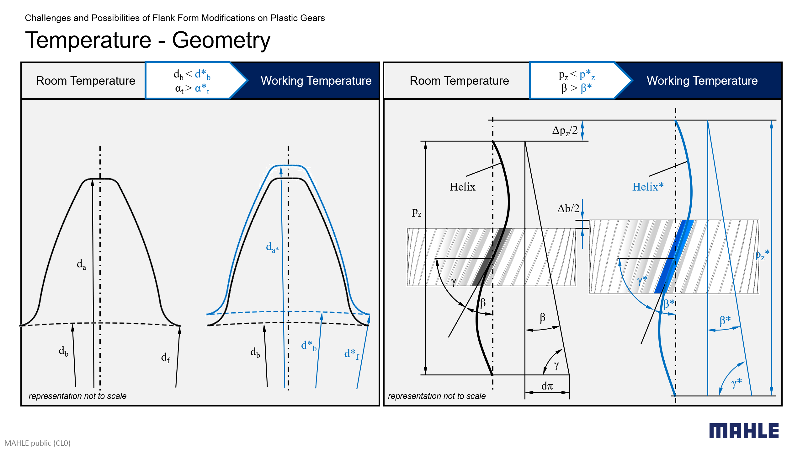
In metals, the change in Young’s modulus within the typical temperature range is negligible, whereas for plastics, it is significant. For example, the secant modulus of POM can decrease by a factor of 2.4 in the range from -40°C to 90°C [1; Delrin 100nc10]. Due to thermal expansion, temperature changes lead to geometric changes. In the case of identical materials for pinion and wheel the isotropic thermal expansion and contraction primarily affect the gear mesh via an apparent change of the center distance (provided the center distance is not similarly affected, which would compensate for the expansion of each individual part). In the case of different materials for pinion and wheel (e.g., steel to plastic), the expansions in the gear partners are unequal due to the higher thermal expansion of one partner relative to the other. This affects the actual base circle and the resulting involute curves through (assumed) homogeneous, isotropic thermal expansion of the entire gear. This leads to a change of the actual working pressure angle in the gear mesh. The axial expansion of a helical gear alters the helix pitch and, consequently, the helix angle on a defined diameter. When measuring a homogeneously and isotropically expanded gear on a CMM machine with respect to the nominal gear parameters, the measured profile and lead show deviations in both the profile angle and the helix angle, respectively.
Manufacturing Aspects
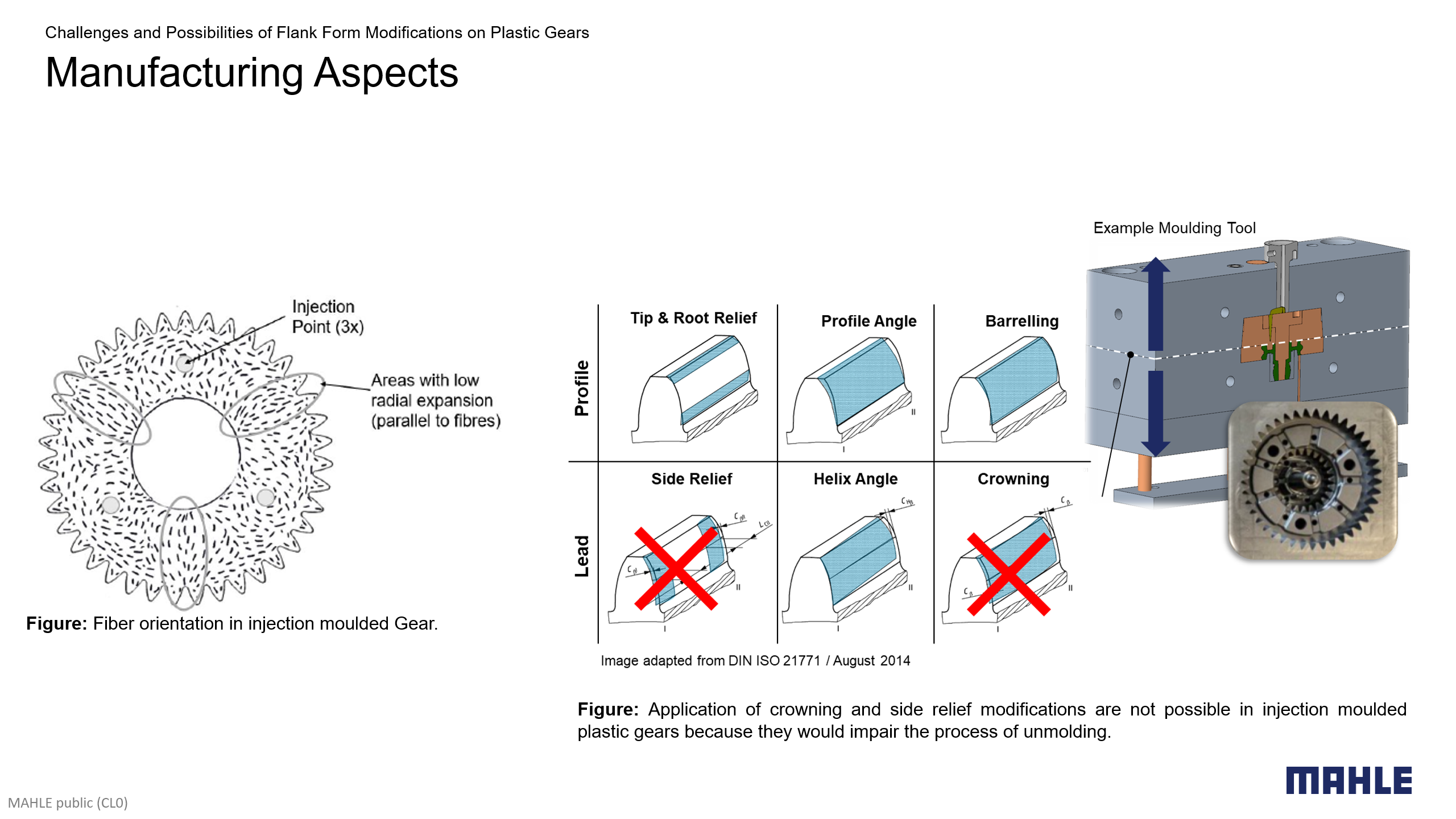
The manufacture of plastic gears using injection molding differs significantly from steel gear production in terms of the achievable accuracies and applicable flank form modifications. Injection-molded plastic gears typically achieve 3–4 quality levels lower than ground steel gears per ISO 1328-2013. Unreinforced plastic components achieve better qualities than fiber-reinforced ones. In short-fiber-reinforced, anisotropic plastics, thermal expansion is not uniform, leading to additional challenges:
Consider a test specimen made of PA66 with 30% short glass fibers which exhibits thermal expansion perpendicular to the main axis that is almost five times higher than parallel to it (100E-6/K vs. 25E-6/K [1; Durethan AKV30]). For example, take the injection molded gear with face-side injection points produced from the same material as illustrated in the figure. As it is typical for such gears, the fibers are significantly more aligned with the radial direction at locations in the center between neighbouring injection points. Even if a gear is perfectly round at room temperature, a temperature increase causes significant roundness deviations. If we assume that for the sketched example gear the anisotropy is 50% smaller compared to the elongated test specimen, i.e., assuming thermal expansion coefficients of 80E-6/K (perpendicular) vs. 40E-6/K (parallel), an additional runout of approximately 0.1 mm occurs at 80°C.
Certain micro-geometries, such as lead crowning, are limited in injection molding due to demolding requirements. The influence of tolerances can be captured through Monte-Carlo simulation. At MAHLE ZG Transmissions, the in-house MimEar module “VarAna” is used to evaluate and optimize micro-geometries under tolerance influences.
Analysis of an Example Gear Pair
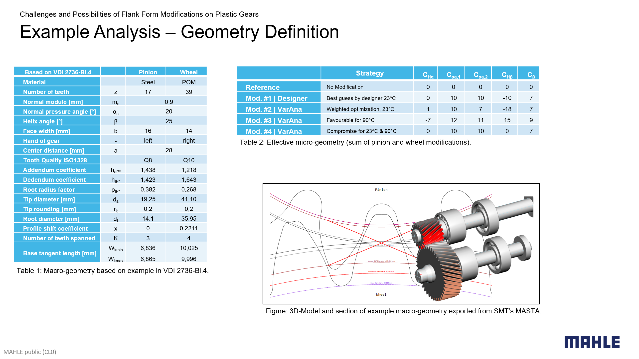
An example gear mesh based on the VDI test gear was modeled in SMT's MASTA. A helical gear macro-geometry with a similar flank profile was derived and a tooth thickness correction was applied to account for the mixed steel-plastic material pairing (see Tab.1). Different micro-geometry variants were investigated (summarized in Tab.2). For the steel pinion, a machining process is assumed, producing lead crowning for the baseline correction. POM was chosen as material for the mating gear, as it is relatively sensitive to environmental influences, showing considerable changes in stiffness and high thermal expansion.
The static peak-to-peak transmission errors for the modeled gear pair were obtained from MASTA's loaded tooth contact analysis (LTCA) considering extended tip contact as described in [5]. The LTCA is based on the assumption of linear elasticity and the validity of the Hertzian contact model. The values for the Young's moduli and the Poisson's ratios must be chosen for each load case and temperature based on the expected strains in the contact.
Example Geometry Definition
- Example gear mesh modeled in SMT's MASTA.
- Based on test gears described in VDI 2736 Blatt 4.
- Helical gear macro-geometry with a similar flank profile was derived and a tooth thickness correction was applied to account for the mixed steel-plastic material pairing.
- The different flank micro modification variants were derived from different optimization targets.
Influence of Load and Thermal Expansion
- Temperature affects both stiffness and geometry.
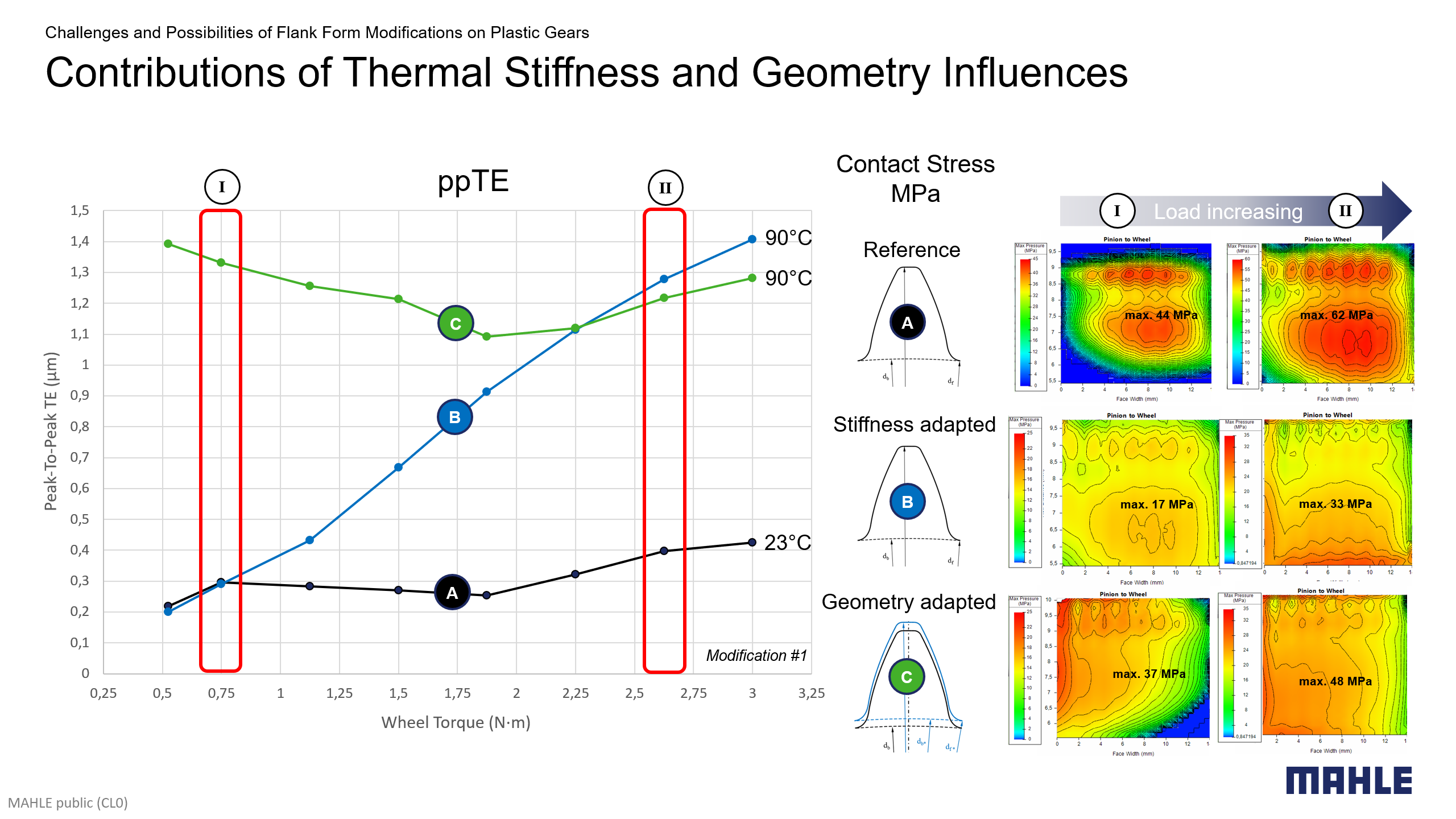
- It is interesting to observe the individual contributions of both thermal effects on the ppTE vs. torque performance.
- At lower loads, thermally induced geometry change dominates.
- As load increases, the thermally induced loss of stiffness gains relative importance.
Comparison of Different Microgeometry Variants
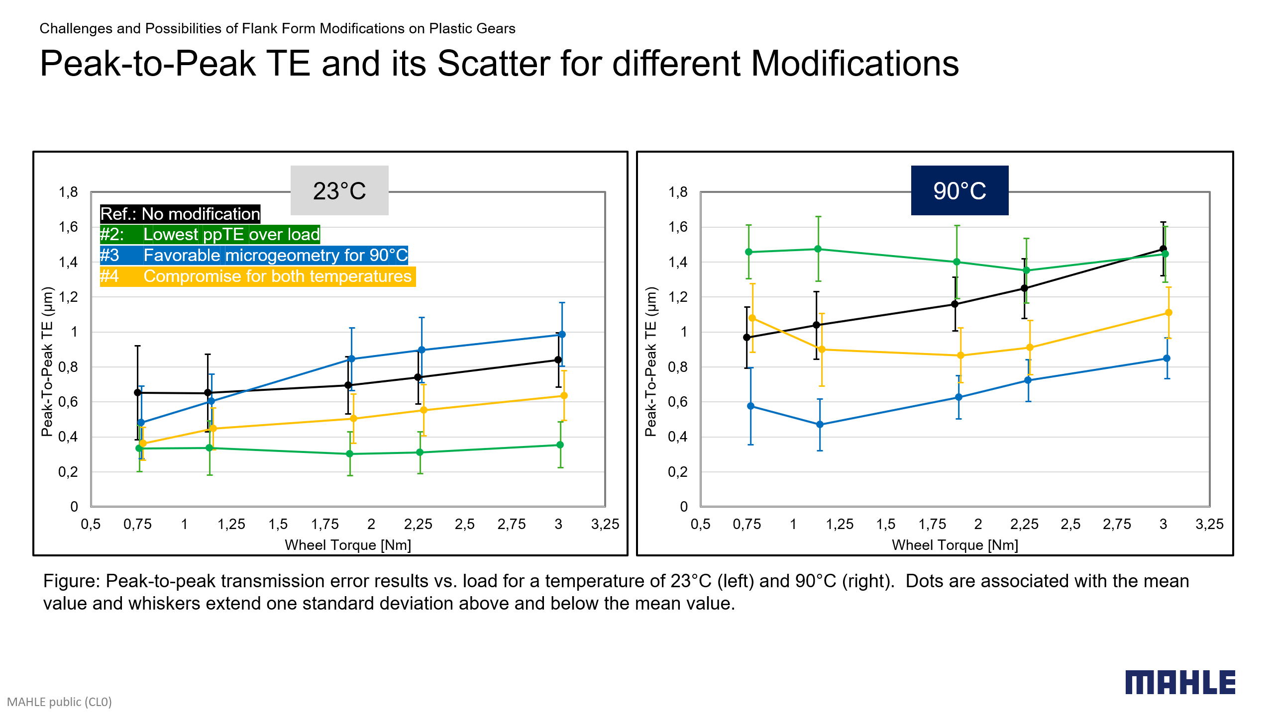
- Peak-to-peak transmission error results vs. load simulated for 23°C and 90°C.
- Diagrams contain mean values and spread obtained from the Monte-Carlo simulation.
- Dots indicate the mean value, and the bars extend one standard deviation above and below the mean value.
Influence of Load and Thermal Expansion
A temperature increase from 23°C to 90°C results in a profile angle change which corresponds to a linear profile relief of approximately 32μm at the gear, while the steel pinion experiences only about 3μm, reflecting the ratio of thermal expansion factors. Changes in the helix angle at the pitch diameter (corresponding to a linear lead modification of -44μm for the POM gear vs. -6μm for the steel pinion) shift the contact pattern and require an adapted micro-geometry. The geometric changes caused by this temperature increase are within the range of ISO 1328 quality grade 11.
Using MASTA's LTCA [5], peak-to-peak transmission errors (ppTEs) were determined for various combinations of torques and temperatures. Initially, thermal expansion effects were excluded (in Fig.: Curve A, black & curve B, blue). At room temperature (23°C), ppTE values increase by a factor of approximately 2 with increasing load. At a temperature of 90°C the equivalent increase of ppTE is greater due to the reduced secant modulus (approx. factor 7). Accounting additionally for geometric changes from homogeneous, isotropic thermal expansion (in Fig.: Curve C, green) affects primarily ppTE values at lower loads, where load-induced deformations are less dominant and the relative proportion of geometry changes is larger compared to higher loads. Interestingly, the elevation of the ppTE under low loads flattens the ppTE vs. torque curve and the ratio of max. to min. ppTE reduces. With increasing loads the curves B and C converge as load-induced deformation dominates.
Comparison of Different Micro-geometry Variants
Different micro-geometries (summarized in Tab. 2) were investigated for 23°C and 90°C. Modification #2 is a micro-geometry found by torque-weighted optimization (minimum RMS ppTE over all torques) at 23°C using MimEar-VarAna and is considered a suitable compromise for the analyzed load range. Modification #3 is the result of the similar process but for 90°C. Consequently, modifications #2 & #3 exhibit the lowest transmission errors across the entire load range at their respective temperatures. However, micro-geometries optimized for only one temperature perform considerably worse at other temperatures. Modification #4 demonstrates a more favorable compromise, achieving satisfactory ppTE values at both temperatures. Interestingly, even the uncorrected gear mesh “Ref.” performs better than temperature-specific optimized modifications used at the respective other temperature. This underscores the need to consider temperature changes in micro-geometry optimization.
Robustness Analysis
Statistical methods can be applied to assess the robustness of a gear design with regard to manufacturing deviations. The dispersion of the ppTE values, which are represented by the whiskers in the result diagrams, were obtained from a Monte-Carlo simulation. Flank- and helix angle deviations were modeled as normally distributed random variables in MASTA's parametric study tool. The mean values were chosen corresponding to a ISO1328-2013 quality of 10 for the plastic gear and quality 8 for the steel pinion. The standard deviations were estimated from (max - min)/6. Likewise, normally distributed deviations of the lead crowning and the tip relief were specified with maximum values of 3μm (pinion)/10μm (gear) and of 5μm (pinion)/10μm (gear), respectively. The scatter bands of ppTE show that uncorrected gears or micro-geometries optimized solely for a narrow operating range, e.g., the temperature-specific designs #2 & #3, tend to show higher tolerance sensitivity at lower loads. Generally, scatter decreases at higher loads, as load-induced deformations increasingly dominate the geometric deviations.
General Recommendations
Compared to steel gears, the micro-geometry design for plastic gears requires a more comprehensive consideration of the influencing factors. Particularly thermally induced stiffness- and form deviations are key factors. Designs with higher lead crowning generally result in a narrower ppTE scatter, but this comes at the expense of a generally higher level of ppTE values. Micro-geometries optimized for a specific temperature may perform unacceptable under other conditions. Especially for helical gears, temperature-induced changes in helix angles lead to unfavorable effects on contact patterns and transmission errors. To minimize thermal influences in particular, the following is recommended:
- Selection of materials with similar thermal expansion.
- Robust design considering thermal influences.
- Smaller helix angles for more stable results.
Short-fiber-reinforced plastics reduce thermal expansion and stiffness variation but lead to larger form deviations. These deviations within the specified tolerances should generally be considered in the design process using statistical methods.
References
| [1] Chemie Wirtschaftsförderungs-GmbH (Hrsg.): CAMPUS [online]. Frankfurt/Main: CWFG mbH, 2025, erhältlich im Internet unter www.campusplastics.com |
| [2] DuPont Engineering Polymers (Hrsg.): Delrin Acetal Resin Design Guide – Module III. Wilmington: DuPont Engineering Polymers, 2024 |
| [3] Frank, A.: Kunststoff-Kompendium. Würzburg: Vogel Buchverlag, 2000 |
| [4] Koop, M.; Melnikov, E.; Merz, V.: Design Investigations and Indications for Acoustical Optimized Gear Meshes Using Plastic Gears. VDI-Berichte 2294, 2017, VDI Verlag GmbH |
| [5] Langlois, P.: Tooth Contact Analysis - Off Line of Action Contact and Polymer Gears. GEAR-TECHNOLOGY September/October 2017 |
You need support with the application of plastic gears in your product?
Contact us for a free initial consultation.